
The BARLOG Plastics diary
Read more
3 tips for designing plastic components for injection molding
Injection molding is one of, if not the most important process for plastics processing. Particularly with regard to the carbon footprint, plastic can be a gamechanger, especially when it comes to substituting metals. However, in order to produce high-quality and economical components, an injection-molded design is crucial. A well-thought-out design of plastic components enables efficient and defect-free manufacturing and minimizes scrap, costs and production times. Here are three important tips for designing plastic components for injection molding:
1. Avoid sharp edges and corners:
Sharp edges and corners in the component can lead to problems during injection molding, such as localized overheating due to high shear, which in turn can lead to material damage. It is therefore advisable to use generous radii at the transitions between component surfaces to ensure even material distribution and minimize potential defect locations. Often, production-related radii are created during tool manufacture anyway.
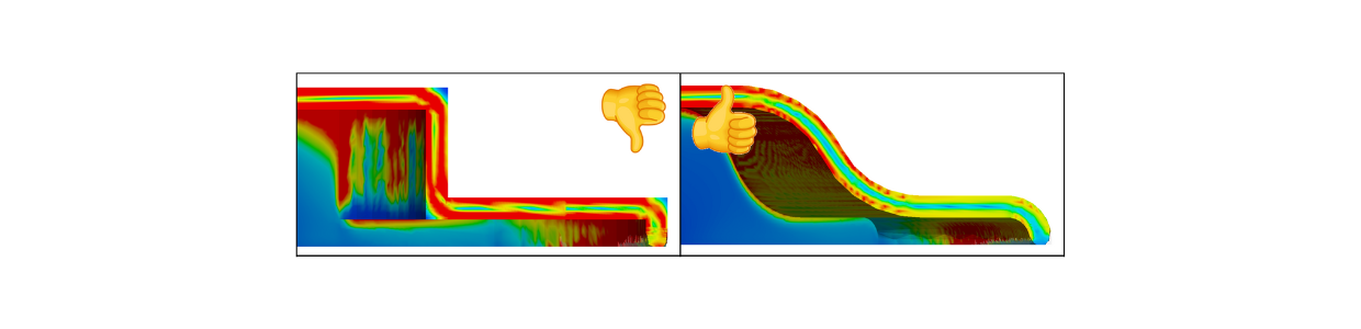
Simulated shear rates
- Consider demolding design:
Demolding is a critical and often neglected step in the injection molding process where the finished part is ejected from the mold. Careful design of the parting line and placement of the ejector elements is critical to ensure smooth demolding and avoid damage to the part and mold. It is advisable to place the demolding line at easily accessible locations in the component and to avoid complex or deep undercuts to facilitate the demolding process.
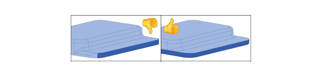
Visualization of the mold separation
- Optimizing wall thicknesses:Wall thickness is a crucial factor in injection molding, as it has a direct influence on the filling of the mold, cooling time and component strength. It is advisable to make the wall thicknesses as uniform as possible and to avoid unnecessary variations in order to ensure uniform cooling and thus avoid additional stresses in the component. Wall thicknesses that are too thick lead to longer cooling times (the influence of the wall thickness is quadratically included in the cooling time calculation – double the wall thickness leads to 4 times the cooling time) and promote distortion, while wall thicknesses that are too thin can lead to insufficient filling of the mold. An optimum wall thickness can be precisely determined in the first step with the help of empirical values and then by simulations to ensure an economical and high-quality injection molding process.
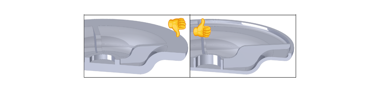
Cover with optimized wall thicknesses
Do you have further questions or need help with the implementation of your project?
Our CAE department will be happy to assist you under the contact options listed below. Feel free to contact us!
Your contact to the author for queries and technical discussions:
Daniel Könemann, M.Eng.
Engineering & CAE
+49 2206 90851-100
daniel.koenemann@barlog.de
www.barlog.de

More news
Press review

“Samplistick” – Sustainable project support from the idea to series production
Read more
Press review

New tool for product carbon footprint
Read more
Press review

Plastic injection moulding – analyse and compare products
Read more
