Engineering & CAE
With our CAE (Computer-Aided Engineering) services, you can accelerate your product development and optimize your products. Whether through virtual molding or FE structure analysis: We support you competently and quickly in virtual space – from the idea to series production.

Accelerated product development
Comprehensive material and process know-how
Minimize project costs
What our customers say


With virtual molding and FE analyzes, quickly and reliably from the idea to the series
In the permanent “time-to-market” race, product life cycles and thus also product development cycles are becoming shorter and shorter. Traditional product development reaches its limits here – often associated with expensive and lengthy adjustments in the later project phases. The result: missed deadlines, unplanned costs and dissatisfied customers. The use of CAE makes it possible to realize a large part of the product development virtually and to achieve better products much faster. Simulation identifies neuralgic points in the design at an early stage and thus enables a reduced use of materials and a design that is suitable for loads and tools. Expensive change loops in a late project phase can thus be prevented.
Error prevention instead of error detection
The Rule of Ten for defect costs shows how significant the cost reduction can be. It defines that the costs for an undetected defect increase by a factor of 10 per value creation stage.
Conversely, this means that a development phase that is optimally supported by computer-aided engineering (CAE) saves costs because errors can be detected and eliminated more quickly in the value chain. The focus is always on error prevention and not on error detection at a later stage of the project.

Integrative simulation
In particular, the coupling of process and load simulation and the automatic processing of extensive variant tests by means of DoE (Design of Experiments) lead to considerable savings.
In our CAE Services (Computer-Aided Engineering) business unit, we offer, among other things, the execution of injection molding simulations, FE structure analyses and component development, individually or combined in a package, as a service. We work with state-of-the-art software packages.
Your benefits at a glance:
The benefits of our CAE services

Leverage virtual product development through CAE to identify early design neuralgic points and reduce time-to-market.

Our many years of experience in the selection and processing of engineering plastics & high-performance polymers is your added value in our development services.

Error prevention in the early project stage through CAE, since the cost of an undetected error per value-added stage increases by a factor of 10.

Identify critical areas of the article and realize them via a load- & tool-appropriate design with a reduced material input.

We attach great importance to validation: our simulation engineers always accompany the initial sampling of previously simulated prototypes at our company.

Agile methods and development assignments closely interlocked with our customers: A cooperative partnership at eye level as the key to success!

By simulatively shifting the weight to the beginning of the development (front loading), errors are avoided instead of being discovered later.

A simulation result is only as good as the material data entered at the beginning. If data is missing or if there are doubts, we can fall back on our own test laboratory.

Our engineering team works together in an interdisciplinary manner and is trained close to practice: Dual apprenticeships in the fields of design, tool mechanics or plastics molding.
CAE & Engineering - From your inquiry to order fulfillment.
 Request a quote and upload data
 Advice on the service/scope
 Quotation preparation within 2 working days
 Commissioning of the engineering service
 We do the job in close consultation with you
 Discussion of the results
 Satisfied customer - thank you for your trust!
simulation
The art of plastics lies in correctly predicting the material’s behavior in the injection molding process and to take this into account in the component and mold design. (…)
FEA
FE structural analyses are used to model and calculate the geo-metries and load cases of a component or assembly. (…)
Simulation
Injection molded articles in the direct vicinity of power batteries, electric motors and other heat other heat radiating power sources can bring economic as well as function-integrative advantages. (…)
optimization
How much material is necessary for a component to withstand the required loads? How do I achieve the maximum stiffness with the minimal use of material? (…)
simulations
Are you considering replacing a sintered solenoid with an injection-molded solenoid in order to tap new economic reserves? (…)
Article development
Do you need help with the implementation of your idea in the form of plastic components? You don’t know whether your plastic component can be produced by injection molding? You want to replace a metal component with plastic? (…)
Benefit from our many years of experience as plastics experts in your development work. We are at your side to advise you in project work on all aspects of plastics. (…)
Manufacturing
In DFM analysis, our engineers evaluate manufacturability at an early stage of the project based on your article design or molding concepts. The early optimization of part geometry (…)
We bring sustainability into your product development. Our BARLOG ECO-Consulting evaluates
sustainability potentials from the
material selection to series production (…)
about our services?
Then do not hesitate to contact us. Together we will
take a look at your request and will be happy to advise you.
Our application examples
Everything you need to know.
Here you can find more information about our products.
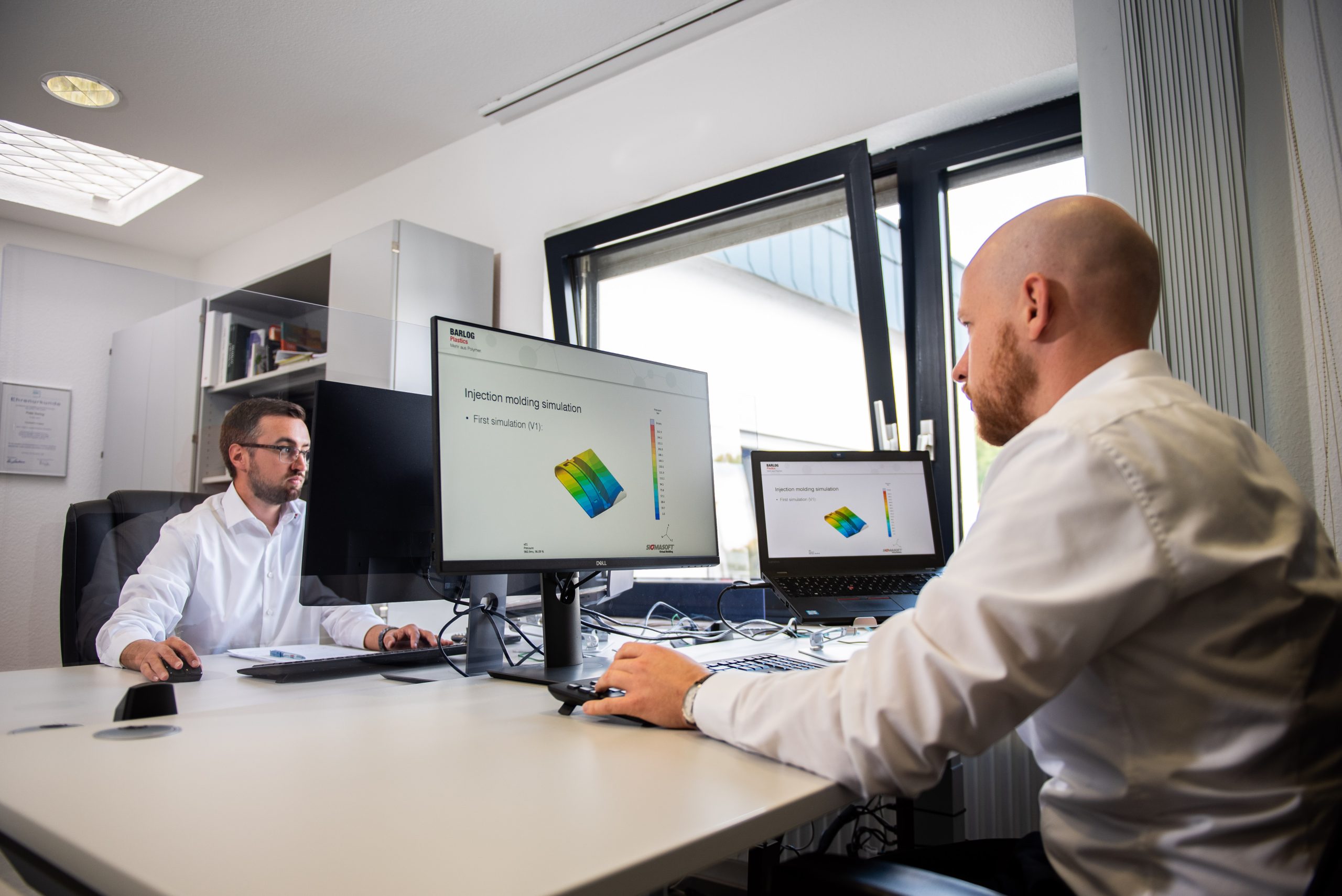
The art in plastics lies in correctly predicting the material behavior in the injection molding process and taking this into account accordingly in the component and mold design. The higher the demands on the quality of the component and the more complex the geometry, the more demanding this task is. Traditional product development quickly reaches its limits, and one risks expensive and lengthy adjustments in the later project phase. The result: missed deadlines, unplanned costs and dissatisfied customers. In our CAE Services (Computer-Aided Engineering) business unit, we offer injection molding simulation as a service for both thermoplastics and LSR (Liquid Silicon Rubber). Depending on the customer’s task, we simulate the various aspects of injection molding using the SIGMASOFT® Virtual Molding software package. The different processes can be used to avoid additional costs and time delays when the mold is actually already supposed to produce components.
Simple filling simulation

Our team evaluates whether a part can be filled with the chosen material, where it is best to gate it, how weld lines and fiber orientations form, and where the risk for surface defects and air entrapment occurs.
Simulation of cooling behavior as well as shrinkage and warpage

Taking into account the holding pressure and cooling phases, we can also simulate shrinkage and warpage, and in this way generate important information for material- and production-oriented component optimization.
Calculation of the thermal budget

We calculate the thermal budget of the entire mold over several process cycles. In this way, we can also detect temperature effects that only build up over time.
Determine and create material data records
We determine material data sets for injection molding simulation, production-oriented optimization of component design and comparison of theory and practice using test molds in the injection molding pilot plant.

DoE (Design of Experiments)
In order to shorten the number of iteration loops in the development of a component, injection molding simulation can be supported by means of statistical design of experiments (DoE). With a view to a target result, the best possible injection molding parameters, gating points or geometry alternatives can be found.

Structural FEA are used to model and calculate the geometries and load cases of a component or assembly. The result can be used for material selection, geometry optimization or strength verification. Simulation makes it possible to identify the neuralgic points in the design at an early stage, thus reducing material usage, enabling a design that is suitable for the load, and preventing expensive change loops at a late stage in the project.
Particularly for plastic parts subject to high mechanical loads, fiber-reinforced materials are often used whose mechanical properties vary anisotropically, i.e. depending on the direction of the fiber orientation. In order to obtain the most accurate calculation results possible, it is necessary to know the fiber orientation and to incorporate it into the structural analysis. In a so-called integrative simulation, the fiber orientations are transferred to the structural analysis and taken into account with the aid of an injection molding simulation. For initial calculations, material comparisons and especially for non-reinforced materials, the model can be simplified to such an extent that integrative simulation is not necessary and normal structural analysis can be used.

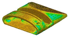
In the injection molding simulation, the filling of the cavity with plastic melt is first calculated. Depending on the injection point, the wall thickness design and the process parameters, a filling pattern results.

The flow processes during filling of the cavity provide for the expression of the fiber orientation through shear and elongation flows, which can also be calculated and represented with the aid of injection molding simulation. The fiber orientation is transferred to the FE mesh and the anisotropic material properties are entered.

With the results obtained in this way, the mechanical load can be predicted much more accurately than with common isotropic calculations. The result: no “fear surcharges” that take the form of unnecessary material consumption and no unexpected weak points due to weld lines or unfavorable fiber orientation.
By coupling injection molding simulation and FE structure analysis, you can achieve even better injection molded parts even faster – with safety and maximum material efficiency.
In order to be able to make a reliable statement about the mechanical performance of your thermoplastic component, we use ANSYS mechanical. Due to the discretization of the component in finite elements, it is possible to calculate complex components. For each finite element a system of equations is solved, which are then combined into an overall system of equations and whose solution can be read and interpreted.
The following list describes various problems and evaluation options that can be investigated and avoided with the help of structural analysis:
- possible deflection of snap hooks
- Material selection
- deformation due to defined load
- resulting stresses
- resulting forces
We provide you with the evaluation of the simulation results with problem areas as well as optimization suggestions in a final report. On request and in case of big time challenges, we can present the results live to you and only derive measures for the time being, so that your time bottleneck does not become even tighter. You will then receive the final report a few days later.

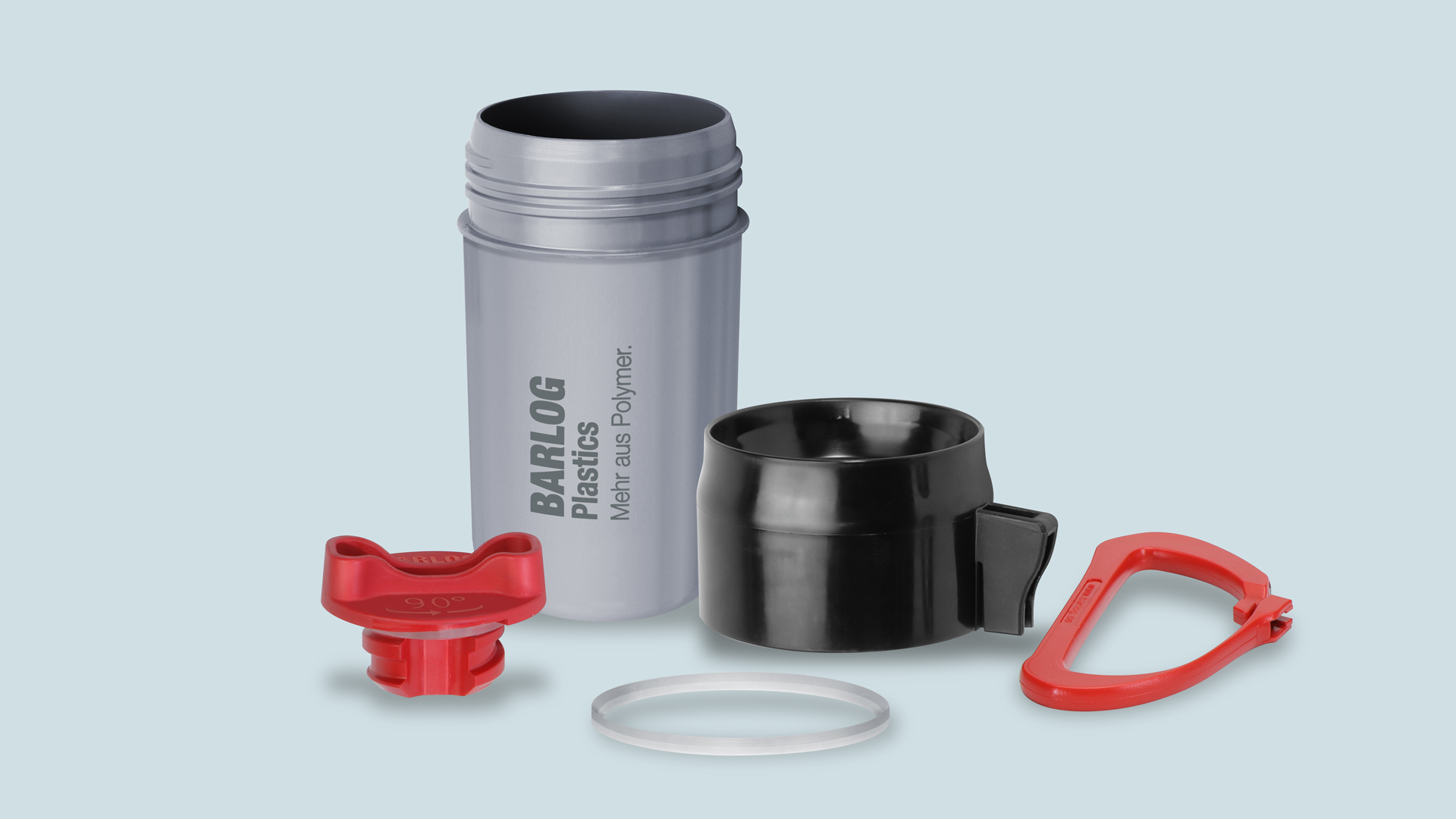
Picture: Load in carabiner 2.0 under tensile load
Is your component subjected to internal pressure in the application? A defined force is acting on your component? Or the snap-fits are deflected by 0.3 mm during assembly? Then it is important to test whether your selected material can withstand these loads and whether the geometry of your component is suitable for the application. Such a check is possible with a structural analysis. The results of a structural analysis can also help you to simulatively test a selection of different materials before you make a final decision.
Injection molded articles in the direct vicinity of powerful batteries, electric motors and other heat-radiating power sources can bring economic as well as function-integrative advantages. But how do thermally conductive plastics (e.g. KEBABLEND / TC) behave in direct comparison to classic polymers or alternative materials with a special focus on their thermal conductivity? Where are bottlenecks in energy transport that can often be corrected with slight design changes, e.g. in the cooling fin geometry?
This is where thermal steady-state or thermal transient simulations of injection molded articles with ANSYS can help. If required, our calculation engineers will show you direct comparisons with other materials in the simulation to increase the understanding of efficient thermal management in conjunction with cost reduction through injection molding production. The issue of thermal expansion and any resulting stresses and deformations can also be investigated by simulation.
Concrete application possibilities:
- Making effects visible in the use of thermally conductive plastics e.g. studies on the cooling of high-voltage batteries or LED sockets
- Clamping/loading with different thermal expansion behavior in assemblies
- Solve problems with heat accumulation / insulation with plastic articles
- Optimization of cooling fin geometry
- Consideration of direction-dependent heat conduction

How much material is necessary for a component to withstand the required loads?
How do I achieve maximum stiffness with minimum material input?
The answer to these questions is provided by topology optimization, a computer-based calculation method in which the optimum component shape is found taking into account the given boundary conditions.
To do this, we first work with you to define the boundary conditions of the optimization, which include the maximum permissible installation space and all unchangeable areas, such as bolt-on surfaces that must not be changed. Analogous to a pure structural analysis, the load introduction and the clamping of the component are determined in the next step.
The FEA program then automatically removes the material everywhere that does not contribute to the stiffness and thus does not absorb any load. In the end, the result is usually a bionic structure that represents the optimum geometry with maximum stiffness and minimum material usage. This material saving results not only in a weight reduction, but also in a cost reduction at the same time.
The results of the topology optimization can not only be used to directly manufacture the component in 3D printing, but also serve as the basis for a design that is suitable for load and production. Through additional boundary conditions, such as the definition of a demolding direction, the constraints of injection molding are already taken into account during the simulation.

Are you considering replacing a sintered magnet with an injection-molded magnet in order to tap new economic reserves?We use FE-based magnetic field calculations to support our customers in the development of injection-molded magnets. Our support begins in the concept phase, where we investigate and evaluate initial concept ideas with regard to feasibility in magnetic injection molding. When designing the magnets, we naturally always keep an eye on the subsequent manufacturability in the injection molding process right from the start. Here, we combine our many years of know-how in the field of magnet materials with our wealth of experience in design suitable for plastics. The combination of rheological and magnetic component design provides our customers with the decisive acceleration effect in the development and implementation of their products to series maturity. The tasks that are investigated by means of magnetic field simulations are of a diverse nature: Design of magnets for sensors (calculation of the flux density as a function of the sensor distance)
- Calculation of permanent magnets (holding magnet, magnetic couplings, magnetic springs, haptic applications, etc.)
- Simulation of rotor magnets for pumps and BLDC motors (flux density profile over the angle of rotation)
- Magnetic design of injection molds for the production of plastic-bonded magnets

Do you need help with the implementation of your idea in the form of plastic components?
You don’t know whether your plastic component can be produced by injection molding?
You want to replace a metal component with plastic?
Then you have come to the right place! BARLOG Plastics GmbH offers you an “all-round carefree package” for the article development of injection-molded plastic components.


Contrary to the widespread guideline from the textbook to use constant wall thicknesses in the entire component, post-pressure-optimized jumps in wall thickness are in many cases the better solution for injection-molded design – from the injection point close with thicker walls to thinner wall thicknesses at the end of the flow path. Using the example of an edge protection bracket, the variable wall thickness profile has led to an enormous improvement in the supply pressure, which could be analyzed using an injection molding simulation.

Benefit from our many years of experience as plastics experts in your development work. We are at your side to advise you in project work on all aspects of plastics.
Together with our customers, we want to develop the best possible solution for every plastics-related task and conquer new markets together with our customers.
Possible consulting topics:
- Support for the selection of materials
- Feasibility evaluations of your concepts
- Concept development for your ideas
- Series Transfer
- Design for Manufacturing (DfM) Report
- Damage analysis
- Reverse Engineering
- Metal replacement
- Evaluation of tool concepts
- Lifetime evaluation of technical plastic components
Contact us, we will be happy to support you!
In DFM analysis, our engineers evaluate manufacturability at an early stage of the project based on your article design or molding concepts. The early optimization of part geometry, injection mold and injection molding process enables you to reduce molding and development costs and also increase implementation speed and on-time delivery:
Review of the component:
- Mass accumulations/thin spots
- Draft angles
- Undercuts
- Wall thickness variations
- Suggestions for changes are implemented directly in CAD
Injection molding simulations with a view to:
- the pressure requirement during the filling phase
- the risk of potential air inclusions
- the risk of potential weld lines
- the risk of potential flow seams
- the temperature development on the component incl. hot spots
- the risk of potential sink marks
- the cooling behavior of the component
- the expected sealing time
- the holding pressure effectiveness
- the shrinkage and warpage tendencies
- if applicable, inserts and their deflection through the injection molding process
The effects of different gating points and geometry optimizations are documented comparatively.
Proposal for a mold concept:
- Separation
- Slide
- Position of the gating point
- Ejector positions
- Critical venting points in the mold
Effects of minor/allowable part changes on manufacturing costs.
Comparison of the initial version with the optimization in the injection molding simulation.
In summary, based on your article design or molded part concepts, we evaluate the implementation in the injection mold as well as in the manufacturing process itself already in an early project phase and intervene optimizing together with you. In addition to the classic DFM analysis as a representation of the ACTUAL state, we see this analysis as active development support.
We bring sustainability into your product development. Our BARLOG ECO-Consulting evaluates sustainability potentials from material selection to series production.
Sustainability from the idea to series production
We not only work actively ourselves to reduce our carbon footprint (CFP) and improve it along the entire supply chain.
We also support you in becoming more sustainable in your production processes. We look both “upstream” – toward suppliers – and “downstream” – toward customers and their products.
3 service modules, 1 goal: BARLOG ECO-Consulting
1. ECO-Selection
We support you in selecting the right material – while keeping an eye on the resources of our planet.
Whether recycled polymers from post-consumer or post-industrial waste or individual recycled components such as carbon fiber: Based on an existing product, we compare the materials currently used with various material alternatives for you – in terms of material technology, environmental technology, production technology.
2. ECO-Design
Together with you, we develop the best possible component design – also with regard to design-for-repair and design-for-recycling. By means of topology optimization or screening of the injection molding process, we go in search of unnecessary material accumulations. We help you to design your products in such a way that they can be recycled or repaired more easily and completely and are manufactured in a resource-efficient way.
3. ECO-Simulation
We simulate your production cycle – revealing if and where cycle time reductions or better temperature control layouts would be possible. Do you always have several temperature control units with very high temperatures in use? Your temperature control system is always running at full load to maintain the desired surface temperature in the mold? Shorter cycle times, fewer temperature control units or lower supply temperatures as well as precisely placed heating cartridges ensure energy savings – and thus lower CO2 emissions!
Contact us, we will be happy to advise you!

Do you have
questions about our
products or services?
Then make an appointment with us.
Our team will be happy to advise you in a
personal conversation or by e-mail.
